Getting Started
Components
| Component Name | Image |
|---|---|
| BBC micro:bit v2 Go Bundle | 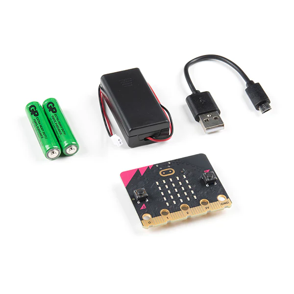 |
| Micro:bit compatible breakout board | 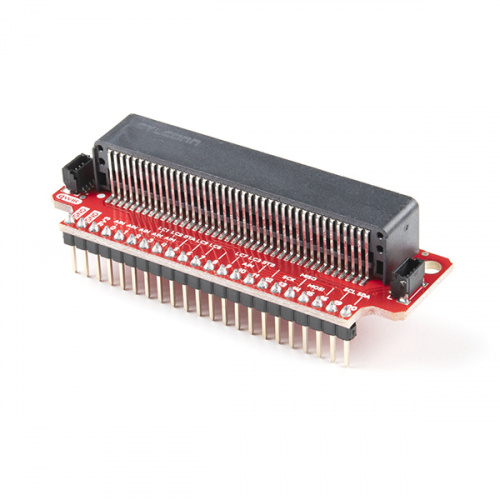 |
| 4x AA Batteries |  |
| Motor Shield V3 | 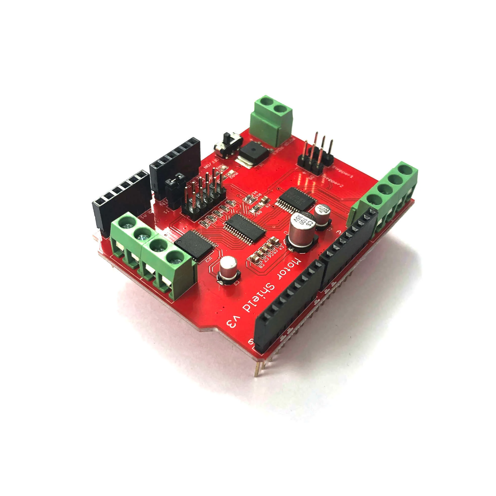 |
| Robot Chassis Kit | 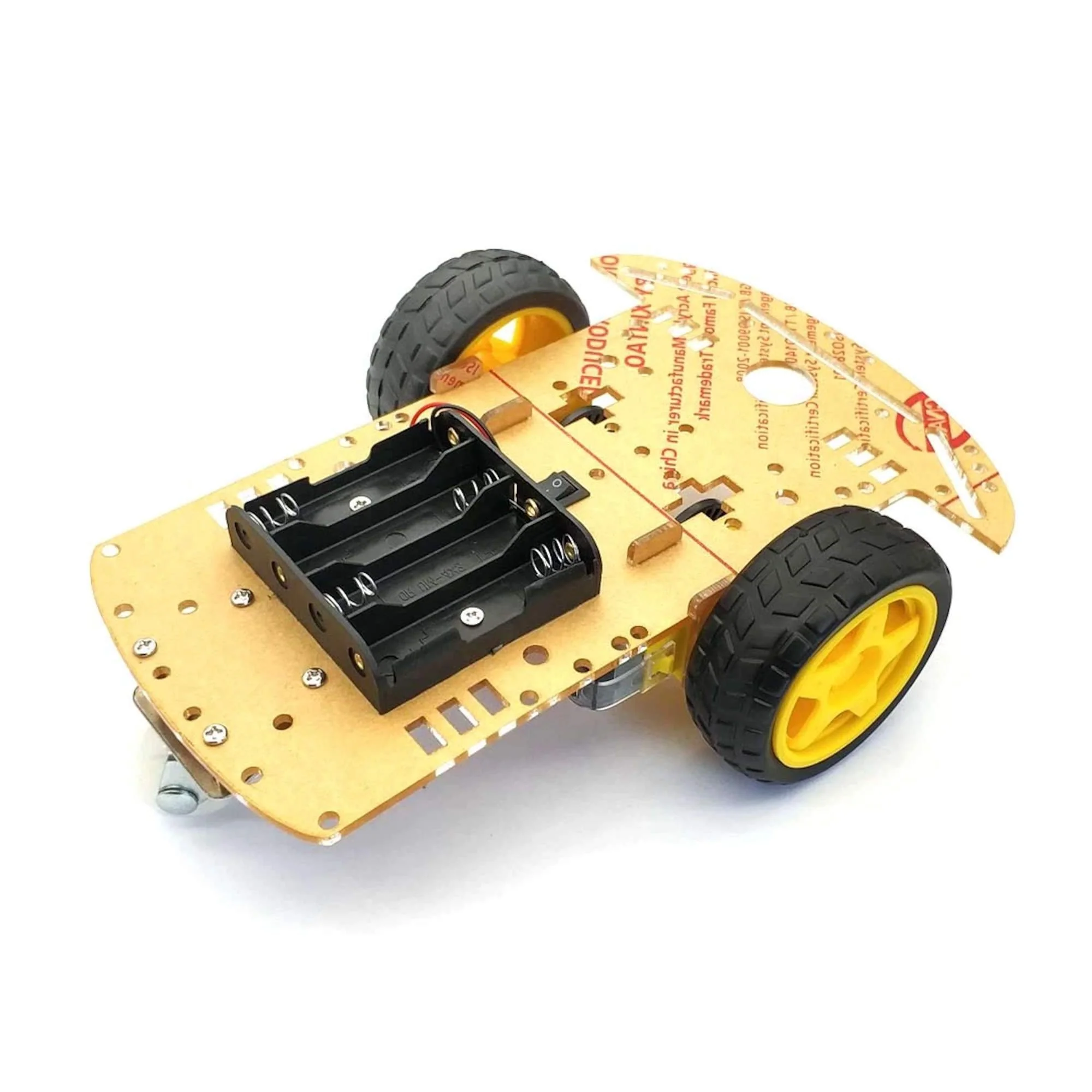 |
| Small Breadboard | 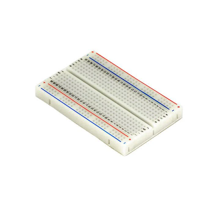 |
| 2x Flex Sensors | 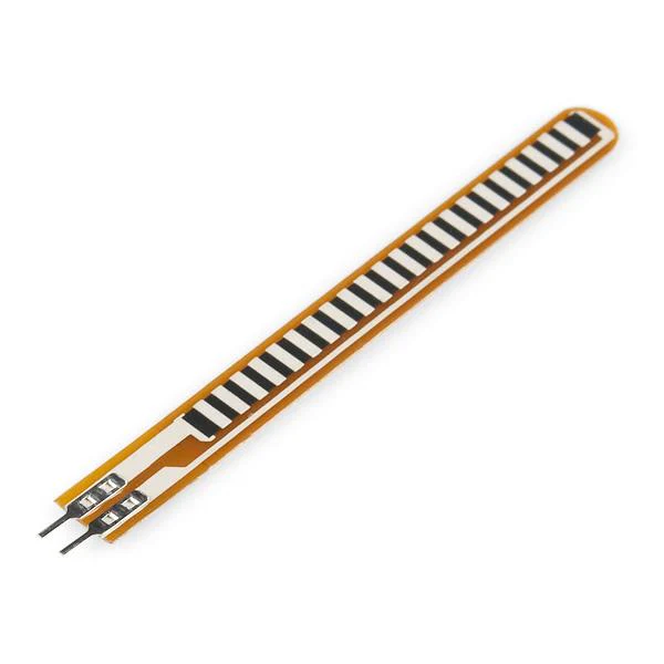 |
| Jumper Wires | 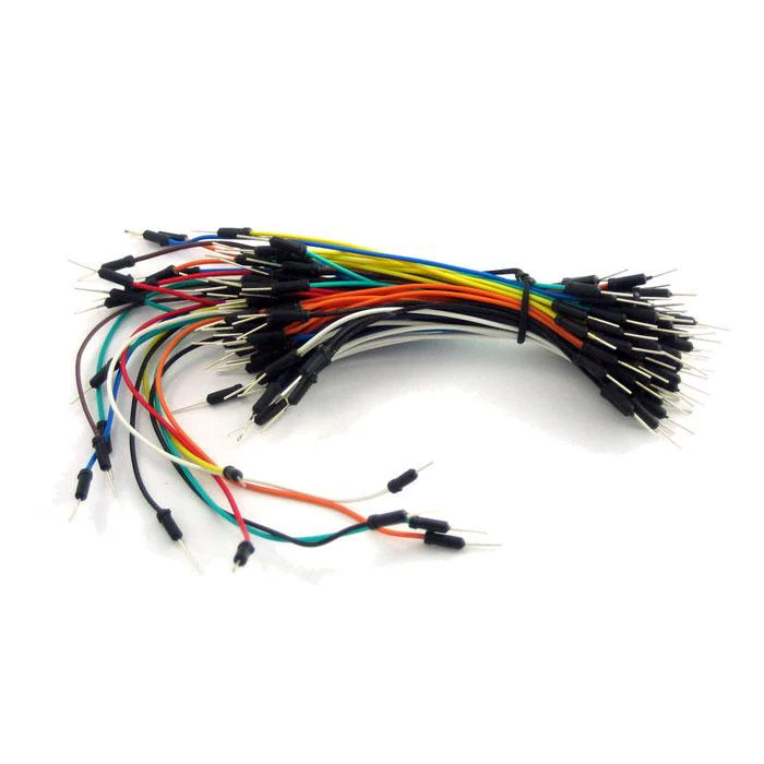 |
| 2x 100nF Ceramic Capacitors | 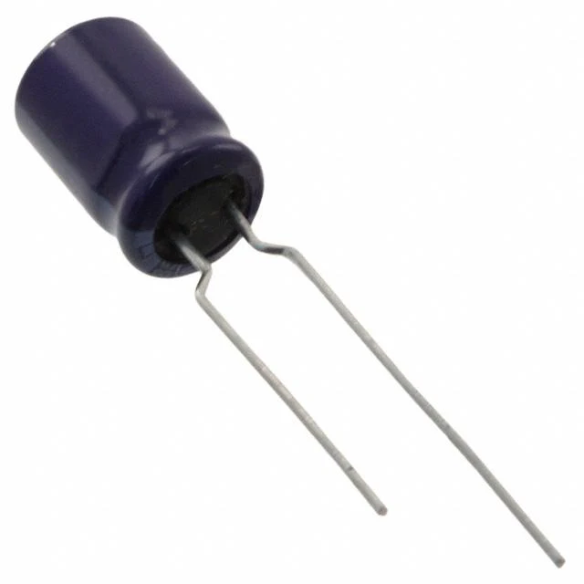 |
| 2x 211 kΩ ±0.5% Resistors | |
| 1x 130 Ω ±0.5% Resistor | 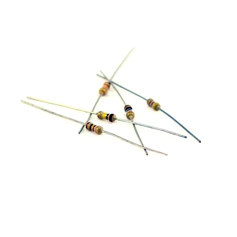 |
| 1x Button | 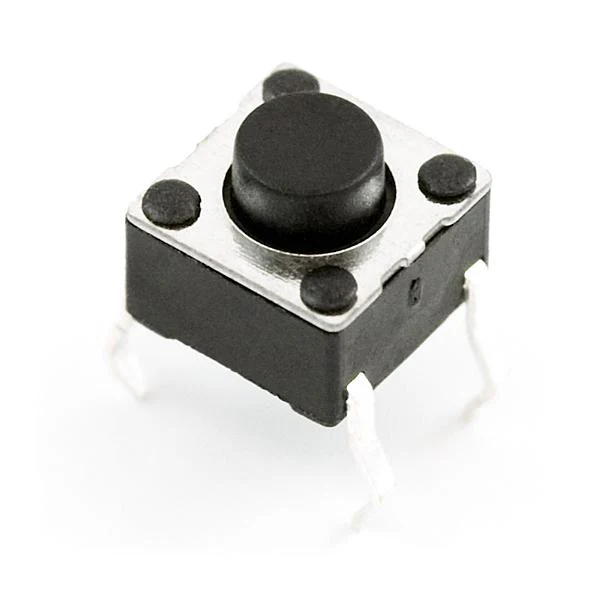 |
Hardware Setup
Keeping the diagram as a reference, here are the connections to be made to the motor shield using jumper wires:

The breakout board we used has a red row and a black row which is used for the 3.3 IN and GND respectively. Connections are to be made to 5V and GND on the motorshield. (Motorshield’s pwr1 IN does not light up and the board logic is not powered with 3.3V).
- PIN 0 and PIN 1 on the micro:bit => A0 and A1 on the motorshield which is in turn connected to the two flex sensors.
- Since we are using M2 and M4, the respective pinouts on the motorshield ie. 11, 12 & 5,6 of the digital pin array are connected to the microbit. (Refer to the CAROBOT Motor shield V3 guide for more information) As for which pins on the micro:bit that the connection is made is flexible. Just has to be one of the GPIO pins. However, care is to be taken that it is not interfering with the microbit display or buttons. If that is the case, they have to be turned off in the code before accessing those pins.
- A4 and A5 on the motor shield are connected to Pin 20 (SDA) AND Pin 19(SCL) respectively. These are not interchangeable as they facilitate the i2c communication.
- Digital Pin 8 on the motorshield is used to complete the button circuit that is used to calibrate the flex sensors. It can be connected to any GPIO pin on the micro:bit, keeping in mind the previously mentioned conditions.
- Finally, the small circuit on the breadboard has to be connected to the Vin and the GND on the motorshield thereby completing the circuit.
Software Setup
The software setup is very simple. It involves flashing the .hex onto the micro:bit by connecting it to a computer using a micro-usb cable. A micro:bit python editor on chrome was used to flash the code onto the microbit as other browser do not allow direct flashing without extra steps.
There are no extra dependencies or libraries since all of the code is written from scratch, taking the logic from the adafruit motorshield library which was written in C.
Additionally, the i2cscanner.hex file which was flashed to check if the i2c connection was up and running since that was the main obstacle while the project was in development.
Note:

There might occur the need to tamper with the values of the constants below depending on what you are reading on the console for the resting values of flex sensor readings. The rest of the logic remains the same.
As for details on the code itself, the documentation as comments on the code should serve as a guide.